
Minimum Draft Angle for Aluminium Die Casting
Technical Expert Insight: Hank, Senior Tooling Engineer at Alumcasting.com Core Domain: High-Pressure Mold DFM Optimization | Friction Matrix Analysis | High...
Request a QuoteTechnical Expert Insight: Hank, Senior Tooling Engineer at Alumcasting.com Core Domain: High-Pressure Mold DFM Optimization | Friction Matrix Analysis | High-Tolerance Ejection Systems
During my two decades in the precision die casting shops of Dongguan and Shenzhen, I’ve seen countless “perfect” 3D designs fail the exact moment they hit the production floor. Why? Because the CAD model ignored the fluid dynamics and mechanical physics of the release phase. Specifically, the minimum draft angle for aluminium die casting isn’t just a generic geometric value; it is the absolute boundary line between a flawless component and a scrap bin filled with costly drag marks.
Many hardware designers treat the die casting mold like a static box. However, at 700°C, molten aluminium acts like a living beast. As it chills inside the tool steel cavity, it contracts and grips the internal mold cores with immense physical pressure. If your draft angles are too shallow, the heavy ejection pins will punch straight through the part before it can successfully release. That is why our cost-down DFM design analysis starts with ejection physics, long before we ever cut steel.
Textbook Standards vs. Real Factory Limits
In generic engineering manuals, for standard alloys like A380 aluminum, you will read about a default 1.5° to 2.0° draft on all internal vertical walls. But what if you are engineering high-complexity thin-wall die casting tooling for an automotive EV housing where package space is severely limited? On the production floor, every millimeter is a hard-fought luxury.
| Feature Configuration | Standard Manual Draft | Hank’s True Factory Minimum |
|---|---|---|
| Outside Cavity Walls | 1.0° | 0.5° (Requires Mirror-Polish Steel) |
| Inside Core Elements | 2.0° | 1.5° (Prevents Solidification Shrink Grip) |
| Deep Pocket Ribs | 3.0° | 2.0° (Must pair with Blend Radii) |
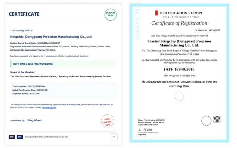 Figure 1: Operating under verified IATF 16949 protocols allows us to push tool tolerances safely to the absolute minimum physical boundaries.
As an IATF 16949 certified supplier, we know that for structural automotive die casting parts, cosmetic surface integrity is just as critical as raw mechanical output. Severe drag scores on a visible structural housing will cause immediate QC batch rejections. Consequently, we often design custom localized variable drafts for premium cosmetic faces to ensure a flawless industrial surface finish.
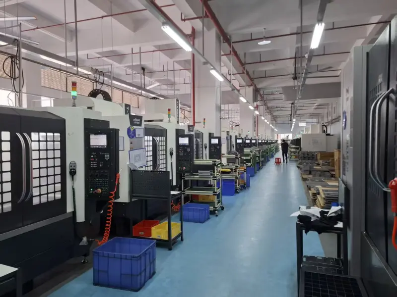 Figure 2: Our internal CNC milling workshop utilizes advanced cutting strategies to achieve perfect draft tapers along hyper-complex tool paths.
Hank’s Secret: The Radii & Blend Connection
Here is a critical truth they don’t teach you in engineering classrooms: The draft angle value is only half the battle. If you do not combine that taper with proper internal corner fillets and blend radii, the shrinking metal will still lock up and ‘pinch’ at the sharp intersections. For complex high-tolerance automotive CNC machining projects, we map out 3D variable drafts that allow ultra-tight linear dimensions at critical mating zones, while opening up the draft elsewhere to make ejection smooth and effortless.
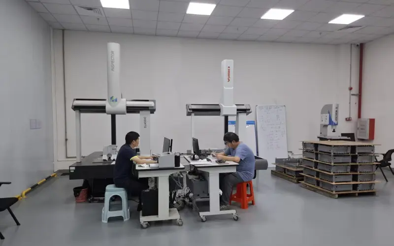 Figure 3: Metrology inspection via CMM ensuring our draft tapers map exactly to the approved engineering CAD model parameters.
Draft Angle Frequently Asked Questions (FAQ)
Q: Can I integrate a zero-draft surface for specific aluminium casting profiles?
A: In standard solid tool tracks, no. However, for specialized interlocking surfaces, we can design automated mechanical slide-cores or moving slides to create zero-draft walls. This setup increases tool complexity but perfectly solves challenging assembly constraints.
Q: Does the specific alloy choice alter the target draft angle requirement?
A: Heavily. Different alloys have distinct linear shrinkage profiles. For instance, transitioning from aluminum to a magnesium-driven matrix via an aluminum to magnesium conversion requires recalculating inner core draft tapers due to distinct solidification fluid behaviors.
Q: How does your foundry handle ultra-deep pocket zones?
A: For deep recesses, draft angles must grow exponentially. If a feature’s depth-to-width ratio breaches a 4:1 scale, a standard 2° angle will fail to break the internal vacuum suction force during ejection, meaning specialized venting or larger tapers become necessary.
Dealing with a challenging geometric configuration that needs an expert technical evaluation? Whether you are coordinating a small batch production run or preparing to scale into millions of units, our engineering division is fully equipped to review your file.
Get a Free DFM Draft Angle Audit Within 24 Hours
Submit your 3D step file or technical drawing today. Our engineering hub in Dongguan will run a professional tool-release evaluation and mold-flow projection to ensure risk-free production scaling.
Ready to start your project?
Talk to AlumCasting engineers about your casting, machining and tooling requirements.