
5000T Die Casting: Max Wall Thickness & Projected Area Limits
An expert 20-year tooling engineer’s guide to understanding the balancing act between maximum wall thickness and projected area limits on a 5000T cold chamber die casting machine. Avoid defects in EV and large structural parts.
Request a Quote“Over the last twenty years standing next to real, fire-breathing heavy machines in South China’s toolrooms, I’ve seen hundreds of automotive blueprints. Many look flawless on a CAD screen. But when you map them onto a massive 5000-ton cold chamber platform, physics takes off the velvet gloves. Let’s talk about what actually happens when projected area fights wall thickness in the die cavity.”
In the world of modern manufacturing, especially with the surge of gigacasting and structural integration for electric vehicles, the call for massive machines like a 5000T press is louder than ever. However, running a 5000T machine isn’t just about ‘scaling up’ your old 800T mindset. It introduces a completely different dynamic between hydraulic clamping force, fluid flow velocity, heat dissipation rates, and thermal contraction stress.
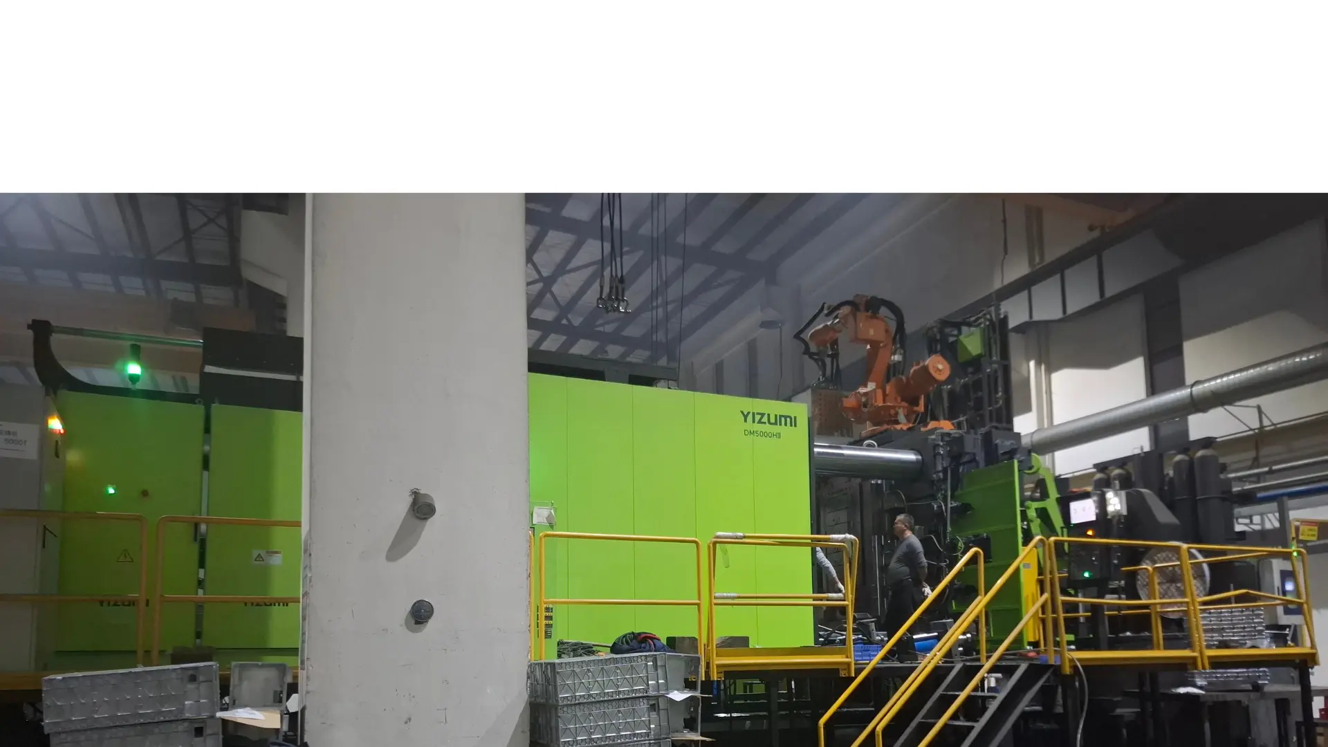 Figure 1: Our 5000T cold chamber die casting floor running large-scale structural components in China.
The 5000T Clamping Force vs. Projected Area Paradox
Let’s strip away the textbook definitions. What is the actual projected area limit? On paper, a 5000-ton machine exerts 50,000 kN of force to keep the moving and fixed die halves closed. When molten aluminum alloy—say, liquid A380 aluminum—is forced into the mold via the plunger at speeds exceeding 6 m/s, it creates an intense internal cavity spike pressure. This pressure typically ranges from 70 MPa to over 100 MPa for high-density structural components.
If your component’s projected area (the flat shadow area of the part plus the entire gating and overflow system) is too vast, the separation force will exceed 5000 tons. The result? Flash, dimensional blowing, out-of-tolerance part lines, or a dangerous spray of molten alloy. For a 5000T machine, your maximum safe projected area generally tops out between 3,500 cm² to 5,000 cm² depending heavily on the target injection pressure.
Hank’s Shop-Floor Reality Check: Many R&D engineers forget to calculate the overflow wells and the runner footprint into the projected area. When designing massive housings, if your part itself takes up 4,200 cm², your runners might push you to 5,300 cm². You don’t need a bigger part redesign; you need a smarter, more compact DFM design for aluminum die casting molds to save that critical footprint.
The Golden Rules of Maximum and Minimum Wall Thickness
In traditional high pressure die casting process quality management, we always chase thin, uniform walls. Why? Because thick walls equal slow cooling, and slow cooling breeds shrinkage porosity. But when you are utilizing a 5000T press to cast an EV battery housing or a rear underbody structure, the rules shift drastically.
- The Maximum Wall Thickness Limit: Ideally, you want to keep local maximum wall sections under 5.0 mm to 6.0 mm. Anything reaching 8.0 mm or above turns into a thermal nightmare inside the die steel. It creates isolated hotspots that remain molten long after the perimeter has frozen, triggering severe internal shrink cavities.
- The Minimum Wall Thickness Battle: Conversely, because the projected area is so huge on a 5000T press, the flow length is incredibly long. If your wall is uniformly 2.0 mm across a 1.2-meter-long part, the aluminum will freeze before reaching the furthest rib, causing cold shuts. You generally need a minimum of 2.5 mm to 3.5 mm base walls for large structural integrity.
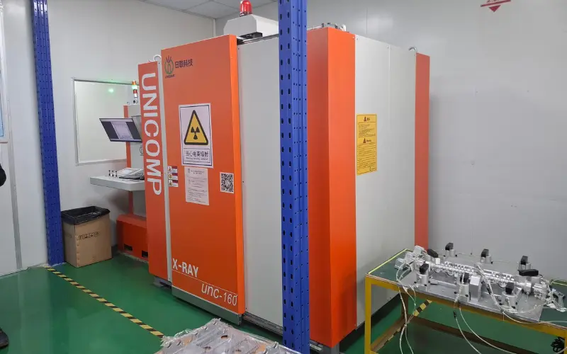 Figure 2: Real-time X-Ray inspection detects deep-seated shrinkage porosity caused by improper thickness balances.
To overcome these harsh limitations without adding unnecessary weight, we often implement advanced rheocasting. If you are struggling with thermal balancing, look into our insights on rheocasting vs conventional HPDC cost analysis. Semi-solid metals flow like toothpaste rather than liquid water, allowing for thick-to-thin transitions without the classic porosity spikes.
5000T Cold Chamber Design Limits: A Reference Dataset
Below is a working threshold table from our project archives here at Alumcasting, based on real-world production setups using standard structural alloys.
| Component Type | Target Alloy | Max Projected Area Limits | Optimal Wall Range | Critical Quality Control Strategy |
|---|---|---|---|---|
| EV Side Member / Rear Underbody | AlSi10MnMg (Ductile) | 4,200 cm² | 3.0 mm – 4.5 mm | Vacuum valve + High-speed squeeze pins |
| Integrated EV Battery Housing Tray | Alloy ADC12 / A380 | 4,800 cm² | 2.8 mm – 4.0 mm | Multi-point gate entry + Squeeze casting |
| Heavy-Duty Telecom Chassis | A356 modified | 3,800 cm² | 3.5 mm – 6.0 mm | Thermal imaging controlled oil cooling |
How We Conquer Porosity in Large-Scale Structural Castings
When dealing with heavy walls or extended projected geometries on a 5000T machine, air entrapment is your biggest enemy. Traditional venting isn’t enough. We rely on sub-10mbar high-vacuum systems paired with strict inspection gates. When we create structural, weldable parts, we use porosity control X-ray inspection for castings to look into the core of the ribs.
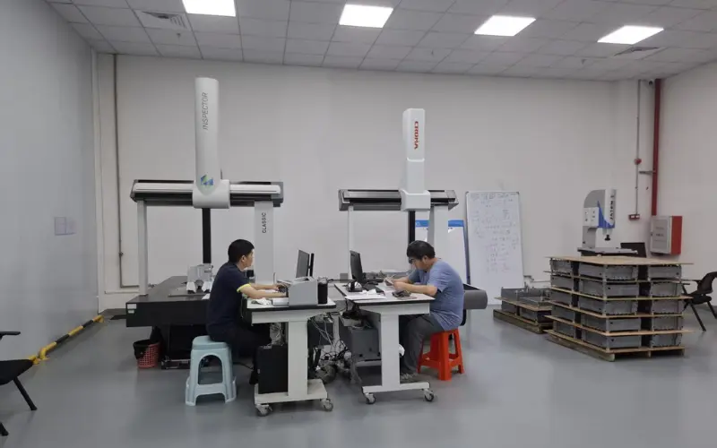 Figure 3: High-precision coordinate measuring machines (CMM) ensure massive projected parts do not warp during cooling.
Additionally, large structural components require highly accurate downstream post-processing. Because the projected areas are so wide, residual stress from cooling can warp a part by several millimeters. Every single massive part we drop from our 5000T lines goes straight through custom stabilization fixtures followed by rigorous verification on our specialized automotive CNC machining and CMM equipment rooms.
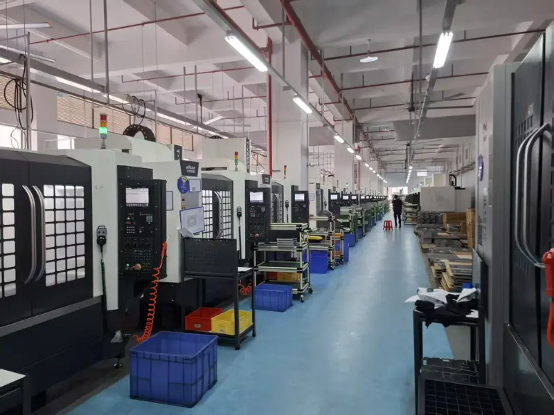 Figure 4: Downstream secondary post-processing at our dedicated CNC finishing bays.
The DFM Balancing Act: An Engineer-to-Engineer Summary
If you take away nothing else from this deep-dive, remember these three practical guidelines when designing for a 5000T cold chamber setup:
- Taper everything you can: Never try to keep a uniform thick wall across the entire length of a huge projected area. Use gradual transitions. See our minimum draft angle guide to understand how shrinkage forces will grab your tooling cores on large-scale parts.
- Ribs are better than bulk: If you need localized stiffness, do not increase the base wall thickness from 4mm to 8mm. Use a grid of intersecting 3mm ribs with generous fillets.
- Partner early on the Tooling Design: A large 5000T mold can weigh over 40 tons. Getting the thermal layout, cooling lines, and runner locations wrong can cost hundreds of thousands of dollars in re-tooling. Work with a partner backed by absolute manufacturing certifications like IATE 16949 high-tolerance suppliers.
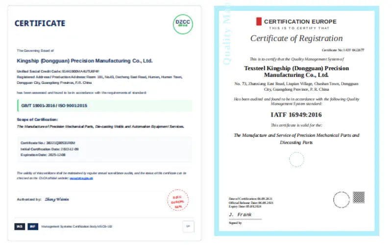 Figure 5: High-stakes automotive components require ironclad international aerospace and automotive standards.
Let’s Get Your Next Large Component Cast Safely
Whether you’re developing an intricate liquid cooling setup—feel free to reference our work on liquid-cooled aluminum plates for EVs—or managing a massive aerospace casting project, understanding the limits of a 5000T cold chamber machine saves time, material, and sanity. Let our 20-year team analyze your CAD and provide a comprehensive, transparent DFM roadmap before the first block of H13 steel is cut.
Ready to optimize your large-scale structural designs?
Skip the guesswork. Fill out the technical questionnaire below to submit your specifications directly to Hank and our senior tooling engineering team for a professional engineering review.
Ready to start your project?
Talk to AlumCasting engineers about your casting, machining and tooling requirements.