
LPDC vs HPDC: Choose the Right Die Casting Process
Technical Foundry Author: Hank, Senior Tooling & Foundry Metallurgist Core Domain: High-Velocity Fluid Mechanics | Controlled Laminar Fill Systems | IATF 169...
Request a QuoteTechnical Foundry Author: Hank, Senior Tooling & Foundry Metallurgist Core Domain: High-Velocity Fluid Mechanics | Controlled Laminar Fill Systems | IATF 16949 Infrastructure
In over twenty years of heavy foundry floor management across Dongguan and Shenzhen, I have seen countless hardware sourcing engineers struggle to choose between low pressure vs high pressure die casting. Often, they make the fatal mistake of looking exclusively at the initial unit price tag. But the truth is, the correct fluid choice depends entirely on your component’s structural complexity, specified wall thicknesses, and long-term mechanical stress limits. We don’t just select a foundry machine; we choose a definitive metallurgical path to component quality.
The “Strength Over Speed” Reality:
“I remember an international client who initially insisted on utilizing standard high-pressure die casting (HPDC) for a load-bearing structural automotive control bracket to minimize cycle time. After the initial batch failed stress-fatigue testing due to internal gas pockets, we shifted the tooling layout to Low Pressure Die Casting (LPDC). That strategic change taught their team that while HPDC offers unmatched velocity, LPDC delivers the solid microstructural integrity that safety-critical components demand.”
High Pressure Die Casting (HPDC): The High-Volume King
When your production roadmap demands 10,000+ complex, thin-walled lightweight enclosures per batch, HPDC stands completely alone. In this aggressive process, we inject molten alloy into a hardened H13 steel die cavity at extreme shot velocities (ranging from 1.0 to 10 m/s), making it the definitive choice for thin-wall die casting tooling down to 1.0mm thicknesses.
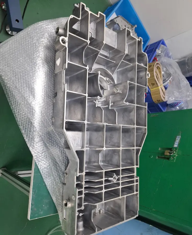 Figure 1: High-precision, complex thin-walled A380 and ADC12 electronic components produced via our automated High Pressure Die Casting cells.
HPDC primarily leverages highly fluid alloys like A380 and ADC12. By fully mastering the A380 aluminum die casting alloy properties, we design parts that strike a perfect balance between surface hardness and raw weight parameters. However, the high-velocity turbulent injection phase inherently risks trapping air. Consequently, we deploy advanced real-time vacuum extraction and rigorous porosity control inspection protocols to keep subsurface voids within strict boundaries.
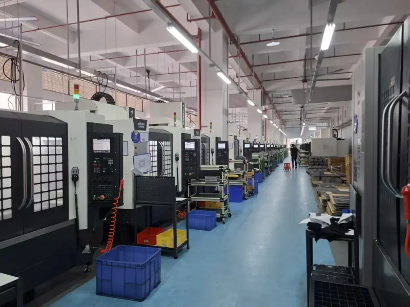 Figure 2: Our multi-axis precision CNC finishing lines ensuring casting split-lines and bearing seats match micro-level geometric expectations.
Low Pressure Die Casting (LPDC): The Integrity Master
In direct contrast, Low Pressure Die Casting fills the mold cavity from the bottom up via a heated riser tube, utilizing highly regulated, low-pressure gas (usually between 0.02 to 0.06 MPa). This clean, upward laminar flow completely eliminates fluid turbulence and prevents gas entrapment. We routinely recommend LPDC for structural automotive die casting parts that demand subsequent T6 heat treatment—a thermal precipitation sequence that would cause standard high-velocity HPDC components to fail due to blister defects.
📐 Engineering Fluid Dynamics Note: Ingate Velocity Control To prevent air entrapment during mold filling, the critical gate velocity ($V_g$) must be kept below the turbulent transition threshold. The fluid flow is governed by the relation:
$$V_g = \frac{Q}{A_g}$$
Where: $Q$ = Volumetric flow rate ($cm^3/s$); $A_g$ = Total cross-sectional area of the ingate ($cm^2$). LPDC maintains a low, stable $Q$ value to guarantee zero-porosity laminar flow.
| Foundry Process Metric | High Pressure Die Casting (HPDC) | Low Pressure Die Casting (LPDC) |
|---|---|---|
| Injection Velocity / Flow Profile | Turbulent Velocity (30 - 60 m/s at gate) | Laminar Slow Rise (Regulated Gas) |
| Minimum Achievable Wall | 0.8 mm to 1.5 mm | 2.0 mm to 3.0 mm |
| T6 Heat Treatment Capability | Prohibited (Prone to surface blistering) | Fully Compatible (Maximizes Yield) |
| Internal Microstructure Density | Standard (Prone to shrinkage centers) | Premium Density (Excellent Fatigue Life) |
| Primary Core Competence | Thin EV Housings & Covers | Heavy Wheels, Thick Structural Arms |
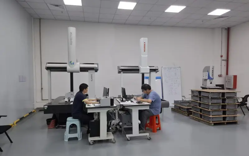 Figure 3: Advanced coordinate tracking (CMM) to verify physical part geometry against target CAD model parameters.
Strategic Scaling & Tooling Lifecycle
Whether your long-term roadmap aligns with the structural density of LPDC or the high-output speed of HPDC, every single program at our facility originates with a thorough, upfront cost-down DFM strategy. For engineering teams developing unverified assemblies, we frequently navigate through an initial bridge tooling phase. This allows us to validate physical shrinkage profiles and mechanical clearances before authorizing full-scale multi-cavity production tooling to scale production smoothly to 10,000 units with zero defects.
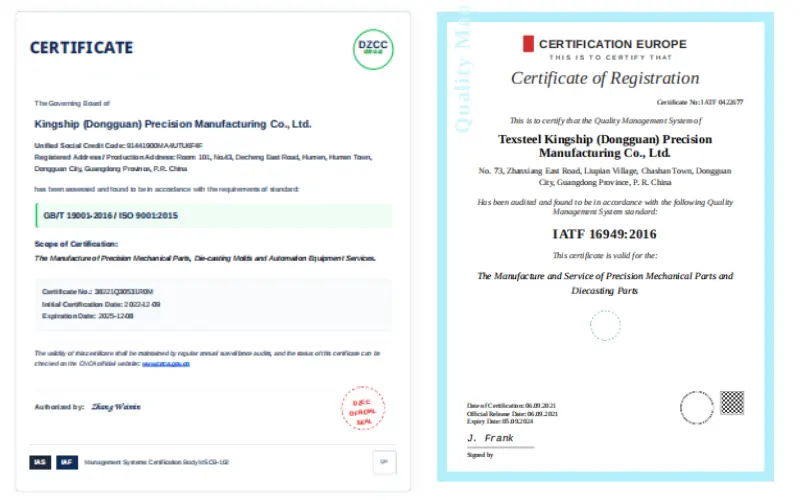 Figure 4: Our operational pipelines operate under verified IATF 16949 tracking frameworks to maintain high batch repeatability.
Expert Selection FAQ
Q: What exactly causes standard HPDC components to blister under T6 heat treatment?
A: The extreme injection velocities of HPDC trap micro-bubbles of gas inside the freezing alloy. When the component is heated to 540°C during T6 solution treatment, these trapped gases expand exponentially, forcing their way to the surface and creating destructive blister bubbles. Our specialized blister-prevention protocols or a shift to LPDC resolve this constraint entirely.
Q: Which casting approach delivers better long-term cost amortization?
A: If your volume amortizes over millions of parts, HPDC yields a lower piece price due to faster cycle times. However, if your part is a load-bearing component that faces dynamic fatigue, LPDC avoids field failures and rework expenses. We perform an exhaustive cost vs. performance analysis to map out the best ROI for your project.
Navigating the boundary lines of metallurgical fluid processes is a highly strategic project milestone. Contact our engineering cell today to submit your 3D STEP models. Our design group will provide a clear DFM feedback report within 24 hours to secure your launch path.
Initiate Your LPDC vs. HPDC Feasibility Evaluation
Unsure which pressure matrix matches your target wall thicknesses and mechanical requirements? Upload your drawings today. Our engineering hub in Guangdong provides complimentary mold-flow simulations and comprehensive tooling cost models.
Ready to start your project?
Talk to AlumCasting engineers about your casting, machining and tooling requirements.